Sunday, December 3, 2017

Small office backup and datastore environment

This post is about my small office datastore and backup enviroment, because "Shit Happens! It's the way you handle it that matters" (cit. Pete Vinken).

My main data store is a pretty old NAS, a Zyxel NSA320, with 2Tb in RAID 1.
I use that NAS for archived jobs, pictures, documentations, downloads, and things that I not often use.


This NAS can install packages from a zyxel offical repository.
A few usufull packages I suggest are:
  • NFS: install NFS server features
  • TFTP: add a TFTP server
  • SMART: Use S.M.A.R.T. (Self Monitoring, Analysis, and Reporting Technology) to monitor hard disks.
If you would like to hack it a bit, you can install a new repository, using instruction from: http://zyxel.nas-central.org/wiki/3rd_party_zypkgs
Once the repository was installed, I've just added a few packages:
  • Dropbear: now I can access the SSH without using any trick, I'm talking about this one http://zyxel.nas-central.org/wiki/Telnet_backdoor
  • RandomTools: some random tools like unrar, nano and so on
  • Tweaks: usefull tweaks like the crontab, a shutdown daemon and so on
  • Entware-ng: the Entware-ng package system, then I've installed
    • openssh-client
    • openssh-server
    • rsync
I use my developement PC as a data store for jobs not archived and that I often use.

My main backup store it is build around two NetGear Stora NAS I've laying around.
The main changes I've made are:
That two store are in my garage. One thing i like from the Stora is that is spin down disk, so power consumption is being reduced.


The four drives on my two store are used for:
  1. my hypervisor backup
  2. Zyxel NSA320 mirror backup
  3. desktop and laptops backup
  4. not used
In a previous post I've talk about my hypervisor and hosts backup, you can find it here: http://davidegironi.blogspot.com/2017/06/vsphere-esxi-backup-strategies-for.html.

The Zyxel NSA320 backup consists of a bash script that uses rsync to mirror the entirire NAS volume over a NFS folder.
In order to make this backup works you have to make a NFS share on a remote device.
Create a share for administrators, this one is optional, you can even put this in your admin share, for now let's suppose the administrators path to be /i-data/______/administrators.
Create a backup folder for data and bin on your Zyxel
$mkdir /i-data/______/administrators/backups/bin
$mkdir /i-data/______/administrators/backups/data
Copy the backup.sh script to the backups/bin folder.
Make the script executable for all users
$chmod a+x /i-data/______/administrators/backups/bin/backups.sh
Edit the script preferences according to your enviroment, you can as example use vi
$vi /i-data/______/administrators/backups/bin/backups.sh
Add the script to crontab, you can access the crontab by the Tweaks package. As example, if you would like to run the script at 2 o'clock at day 5 of week, and have the backup status returned to a txt file, just add the line below to your crontab
  0 2 * * 5 /i-data/______/administrators/backups/bin/backup.sh > /i-data/______/administrators/backups/bin/lastbackupstatus.txt 2>&1

Find the backup script below:
#!/bin/sh

#preferences
LOCALSOURCE=/i-data/_______/
LOCALDESTINATION=/i-data/_______/administrators/backups/data
NFSMOUNTHOST=backupnas
NFSMOUNTPOINT=/home/_______/backups/NAS320

echo "Running backup"
echo ""

#unmount
umount $LOCALDESTINATION
#mount
mount.nfs $NFSMOUNTHOST:$NFSMOUNTPOINT $LOCALDESTINATION -v -o nolock
#check if is mount
if [[ $(nfsstat -m | grep -A 1 $NFSMOUNTPOINT | head -c1 | wc -c) -ne 0 ]]; then
  echo "NFS folder $NFSMOUNTHOST:$NFSMOUNTPOINT mounted on $LOCALDESTINATION"
  echo ""
  rsync -rltxuv --delete $LOCALSOURCE $LOCALDESTINATION
else
  echo "Error: can not mount NFS folder $NFSMOUNTHOST:$NFSMOUNTPOINT to $LOCALDESTINATION"
fi

#umount
umount $LOCALDESTINATION

Note that this script mount the NFS location instead of using rsync over NFS or rsync over ssh. That's because I've notice a better trasfer performance working that way, I'm talking of almost 10Mb/s.

On my developement PC I use two software for backup.
  • Create Synchronicity: find it here http://synchronicity.sourceforge.net/. To mirror the VMWare machines of my development pc over a shared folder. This can be used to syncronize data that does not need to be incremental.
  • Duplicati: find it here: https://www.duplicati.com/. To backup data of my pc over a shared folder. I set up Duplicati with a regex that backups each Project* and Documents* folder, that way all the folder on my main mounted environment that starts with that prefix are been backupped. I can create a new Project tree, like "Projects ESP8266", and that would be added to my backups. Duplicati performs incremental backup, allowing me to reastore data older that 30 days. 
That's almost all about my actual datastore and backup environment.


Notes
  • read risk disclaimer
  • excuse my bad english

Friday, November 3, 2017

ST Audio DSP2000 C-Port on Linux using JACK and wineasio

subtitle:
Make revive the ST Audio DSP2000 C-Post audio board on Linux


I've a DSP2000 C-Post Audio System made by ST Audio (http://www.st-audio.de), I'm using it in my small recording room for instruments and voices, then I usually move to my main workstation to mix in a comfortable environment.
Even if it is a card from the late 90s, it still does a pretty decent job.

This system is build of an external unit and a PCI Card.

See main specs below:
  • 10 x 10 24-bit/96kHz 100% Full-Duplex recording path support
  • 2 x balanced (XLR) inputs with built in pre-amps (-24dB to +50dB) & switchable phantom power (48V)
  • 2 x balanced (XLR) outputs
  • 8 x 1/4" unbalanced inputs
  • 8 x 1/4" unbalanced outputs
  • coaxial and optical & AES/EBU I/O connections as standard
  • stereo headphone output with volume control (1/4" connector)
  • 2 x 16 channel (32 channels) MIDI interface ports provided (2 outputs, 1 input)
  • peak LED for channel 1&2
On this card, all the magic happens in the IC Ensemble Envy24 I/O controller chip, nominally the ICE1712.
The problem with this card it that official drivers just work on Windows 9x/Me/NT/2000/XP, unluckly support for those old O.S. is at the end of life.
But we have an ace up sleeve, it is called Linux.
We can make this card revive, using a brand new, and free also, linux distrubution.
The one I've choose it's Linux Mint 18 (http://www.linuxmint.com/).


As workstation I choose the Reaper Digital Audio Workstation (http://www.reaper.fm/). I'm using this station to record, then i will post mix all on my main workstation, using Reaper of course, this time on Microsoft Windows.
I'm using a Intel Core 2 Duo, 4Gg RAM, 256GbHdd as main hardware cause I do not need a lot of power just to record tracks, of course my mixing workstation is a powerfull i5 machine.

Reaper can works on linux thanks to Wine (http://www.winehq.org/).
The ICE1712 alsa module, which is the linux driver that makes the card works, it is already built in the choosen distribution.
The trick here is to use the WineAsio (https://sourceforge.net/projects/wineasio/) wrapper, to make Reaper works on ASIO (https://en.wikipedia.org/wiki/Audio_Stream_Input/Output) through JACK (http://jackaudio.org/).

So, let's dive into my small guide.

Step 1) Install Linux Mint, of course!

Then we have to add install the KxStudio repository (http://kxstudio.linuxaudio.org/). For my x64 Linux Mint distribution, commands below will works
sudo apt-get install apt-transport-https software-properties-common wget
wget https://launchpad.net/~kxstudio-debian/+archive/kxstudio/+files/kxstudio-repos_9.4.6~kxstudio1_all.deb
sudo dpkg -i kxstudio-repos_9.4.6~kxstudio1_all.deb
sudo apt-get install libglibmm-2.4-1v5
wget https://launchpad.net/~kxstudio-debian/+archive/kxstudio/+files/kxstudio-repos-gcc5_9.4.6~kxstudio1_all.deb
sudo dpkg -i kxstudio-repos-gcc5_9.4.6~kxstudio1_all.deb
sudo apt-get update
sudo apt-get upgrade

VST and wineasio works on x86, so let's set our architecture
sudo dpkg --add-architecture i386

Now we are going to install jack, realtime mode is preferred, when installation ends make the current user part of the audio group using "Administration / Users and Groups: , then logout and login again on your session
sudo apt-get install jackd jack-tools

Commands below will install wineasio, and also wine-rt that is a dependance on wineasio.
sudo apt-get install wineasio
This command will register wineasio, id successfull it should return something like "Successfully registered DLL wineasio.dll"
regsvr32 wineasio

The mudita24 (https://github.com/NielsMayer/mudita24) mixer and alsa-tools should help configuring our card
sudo apt-get install alsa-tools
sudo apt-get install mudita24


Finally, we can install Cadence from the KxStudio tools to enable the ASIO driver.
sudo apt-get install cadence
Once Cadence is installed we have to set the device binded to the driver to Alsa / hw:DSP24.
Then make autostart JACK daemon, and also it could be usefull to route ALSA and PulseAudio to Jack, simply settings the ALSA Bridge to ALSA->Jack

A reboot is preferred now.

Reaper should now recognise the card using the wineasio driver, all should work fine, at least on my hardware.

This card still rules, and can be used at least to record up to 8 tracks.


Notes
  • read risk disclaimer
  • excuse my bad english

Wednesday, October 4, 2017

OpenWrt Guest Routed AP using VLAN with unmanaged switch

I've previously post about a Routed AP for Guest WiFi isolation based on OpenWrt, you can find that post here: http://davidegironi.blogspot.it/2017/09/openwrt-access-point-routed-ap-as-guest.html

This time I would like to make it a little structured, by simply making it modular.
I will build a Guest router, isolated from the main network, that can be used as a gateway for a Guest wired and wireless network.
My guest network should use the same cabled network of my main network, that is using unmanaged switch. Of course if you have managed switch you will get better perfomance cause you can route the guest network to any guest AP or managed swith you want, but in small office and home network managed switch can't always be found.
Our Guest router will produce one tagged VLAN, let's tag it as '2', that will distrubute our Guest network.
The guest router will also serve as a DHCP server for any guest device.
Note that any AP that we want to make act as a Guest AP must accept VLAN traffic.


The OpenWrt configuration is similar to the one proposed in the previous post linked above.

Once again let's suppose we are serving our main network on 192.168.1.0/24 ip ranges, and we would like a guest network, isolated from the 192.168.1.0/24 one, on the 192.168.2.0/24 ip range.

We will make a new switch, that is new VLAN.

On VLAN 1, we disable port 3 and 4, set 5 untagged
On VLAN 2, we enable port 0 and 3 as tagged, 2 as untagged, set 5 tagged
We are going to use port 2 as a wired guest port, port 3 as a tagged guest port for managed switch, and port 0 is the main port that will get the main network signal and "output" the VLAN 2 tagged signal.

/etc/config/network
config interface 'loopback'
 option ifname 'lo'
 option proto 'static'
 option ipaddr '127.0.0.1'
 option netmask '255.0.0.0'

config globals 'globals'
 option ula_prefix 'fd6e:e9df:eb78::/48'

config interface 'lan'
 option ifname 'eth1'
 option force_link '1'
 option type 'bridge'
 option proto 'static'
 option ipaddr '192.168.1.3'
 option netmask '255.255.255.0'
 option ip6assign '60'
 option gateway '192.168.1.1'
 option dns '192.168.1.1'

config interface 'wan'
 option ifname 'eth0'
 option proto 'dhcp'

config interface 'wan6'
 option ifname 'eth0'
 option proto 'dhcpv6'

config switch
 option name 'eth1'
 option reset '1'
 option enable_vlan '1'

config switch_vlan
 option device 'eth1'
 option vlan '1'
 option ports '0 1 5'

config switch_vlan
 option device 'eth1'
 option vlan '2'
 option ports '0t 2 3t 5t'

config interface 'guest'
 option type 'bridge'
 option proto 'static'
 option ifname 'eth1.2'
 option ipaddr '192.168.2.1'
 option netmask '255.255.255.0'

/etc/config/firewall
config defaults
 option syn_flood '1'
 option input 'ACCEPT'
 option output 'ACCEPT'
 option forward 'REJECT'

config zone
 option name 'lan'
 option input 'ACCEPT'
 option output 'ACCEPT'
 option forward 'ACCEPT'
 option network 'lan'
 option masq '1'
 option mtu_fix '1'
 list masq_dest '!192.168.1.0/24'

config zone
 option name 'wan'
 option input 'REJECT'
 option output 'ACCEPT'
 option forward 'REJECT'
 option masq '1'
 option mtu_fix '1'
 option network 'wan wan6'

config forwarding
 option src 'lan'
 option dest 'wan'

config rule
 option name 'Allow-DHCP-Renew'
 option src 'wan'
 option proto 'udp'
 option dest_port '68'
 option target 'ACCEPT'
 option family 'ipv4'

config rule
 option name 'Allow-Ping'
 option src 'wan'
 option proto 'icmp'
 option icmp_type 'echo-request'
 option family 'ipv4'
 option target 'ACCEPT'

config rule
 option name 'Allow-IGMP'
 option src 'wan'
 option proto 'igmp'
 option family 'ipv4'
 option target 'ACCEPT'

config rule
 option name 'Allow-DHCPv6'
 option src 'wan'
 option proto 'udp'
 option src_ip 'fe80::/10'
 option src_port '547'
 option dest_ip 'fe80::/10'
 option dest_port '546'
 option family 'ipv6'
 option target 'ACCEPT'

config rule
 option name 'Allow-MLD'
 option src 'wan'
 option proto 'icmp'
 option src_ip 'fe80::/10'
 list icmp_type '130/0'
 list icmp_type '131/0'
 list icmp_type '132/0'
 list icmp_type '143/0'
 option family 'ipv6'
 option target 'ACCEPT'

config rule
 option name 'Allow-ICMPv6-Input'
 option src 'wan'
 option proto 'icmp'
 list icmp_type 'echo-request'
 list icmp_type 'echo-reply'
 list icmp_type 'destination-unreachable'
 list icmp_type 'packet-too-big'
 list icmp_type 'time-exceeded'
 list icmp_type 'bad-header'
 list icmp_type 'unknown-header-type'
 list icmp_type 'router-solicitation'
 list icmp_type 'neighbour-solicitation'
 list icmp_type 'router-advertisement'
 list icmp_type 'neighbour-advertisement'
 option limit '1000/sec'
 option family 'ipv6'
 option target 'ACCEPT'

config rule
 option name 'Allow-ICMPv6-Forward'
 option src 'wan'
 option dest '*'
 option proto 'icmp'
 list icmp_type 'echo-request'
 list icmp_type 'echo-reply'
 list icmp_type 'destination-unreachable'
 list icmp_type 'packet-too-big'
 list icmp_type 'time-exceeded'
 list icmp_type 'bad-header'
 list icmp_type 'unknown-header-type'
 option limit '1000/sec'
 option family 'ipv6'
 option target 'ACCEPT'

config include
 option path '/etc/firewall.user'

config rule
 option src 'wan'
 option dest 'lan'
 option proto 'esp'
 option target 'ACCEPT'

config rule
 option src 'wan'
 option dest 'lan'
 option dest_port '500'
 option proto 'udp'
 option target 'ACCEPT'

config zone
 option input 'ACCEPT'
 option forward 'REJECT'
 option output 'ACCEPT'
 option name 'guest'
 option network 'guest'

config forwarding
 option dest 'lan'
 option src 'guest'

/etc/config/dhcp
config dnsmasq
 option domainneeded '1'
 option boguspriv '1'
 option filterwin2k '0'
 option localise_queries '1'
 option rebind_protection '1'
 option rebind_localhost '1'
 option local '/lan/'
 option domain 'lan'
 option expandhosts '1'
 option nonegcache '0'
 option authoritative '1'
 option readethers '1'
 option leasefile '/tmp/dhcp.leases'
 option resolvfile '/tmp/resolv.conf.auto'
 option localservice '1'

config dhcp 'lan'
 option interface 'lan'
 option dhcpv6 'server'
 option ra 'server'
 option ignore '1'
 option ra_management '1'

config dhcp 'wan'
 option interface 'wan'
 option ignore '1'

config odhcpd 'odhcpd'
 option maindhcp '0'
 option leasefile '/tmp/hosts/odhcpd'
 option leasetrigger '/usr/sbin/odhcpd-update'

config dhcp 'guest'
 option start '100'
 option leasetime '12h'
 option limit '150'
 option interface 'guest' 

Now we have to add guest firewall rules for guest interface.
This rule has to accept input, accept output, reject forward and Allow forward to destination zones -> lan, this way all the traffic will be forwared to lan.

The lan firewall rule must have enabled Masquerading and MSS clamping, it also have to Allow forward from source zones -> guest, to accept the forward traffic from guest, and Restrict Masquerading to all subnet but not the 192.168.1.0/24, by the value !192.168.1.0/24.

We can now add a guest interface, as bridge and add the VLAN 2 created on port 3.
We are going to set the guest interface with a static address, and enable DHCP for the guest interface assign the interface to the guest firewall zone.

Now we can set the guest WiFi, binding it to the guest interface.


Now we would have a primary WiFi over our main subnet 192.168.1.0/24, and a guest WiFi + a guest wired connection through port 3 of the router over our secondary subnet  192.168.2.0/24.

The Guest router also can act as a guest AP if we would like, by simply enabling the wifi interface and attaching it to the guest interface.

Now that we have build a Guest router, we have to build a AP guest.
There are a few device that can route VLAN network with stock firmware. If we would like to use an OpenWrt firmware, we must enable a VLAN 2 tagged switch on a port, on the same port the VLAN 1 should be untagged.
Then we have to create a guest interface and a guest firewall rule like we've already done.
We can leave LAN interface unmanaged if we do not need to access this AP by the main network.

That's almost all.

So what we have done now: we have a main Router on our main network on the IP range 192.168.1.0/24 and a Guest router on the IP range 192.168.2.0/24. We can use unmanaged switch and run the guest network by using VLAN tagged packets.


Notes
  • read risk disclaimer
  • excuse my bad english

Saturday, September 9, 2017

OpenWrt Access Point & Routed AP with Guest WiFi on AGPF modem/router

The Pirelli Alice Gate VoIP 2 Plus, also known as agpf, is a ADSL modem router with WiFi and Voip capabilities.
The main chip is the BCM6358KFBG, they support OpenWrt.
OpenWrt is a linux distribution for embedded devices, you can find further information on the openwrt website: https://openwrt.org. Although hardware Voip and ADSL is not supported on this router, this device can be pretty usefull for other network roles.

I've saved three of them from junkyard and I start playing with that devices.

This post reports how I've built a Access Point and a Routed Access Point for a Guest WiFi using OpenWrt.
Also a wired guest connection is served.

Let's suppose we are serving our main network on 192.168.1.0/24 ip ranges, and we would like a guest network, isolated from the 192.168.1.0/24 one, on the 192.168.2.0/24 ip range.


The following steps is needed only if your router hasn't OpenWrt on board.
The first step to start the game will be load the OpenWrt firmware.
The following steps may brick your device, so continue at your risk.
You can find a complete guide here: https://wiki.openwrt.org/toh/pirelli/agpf.
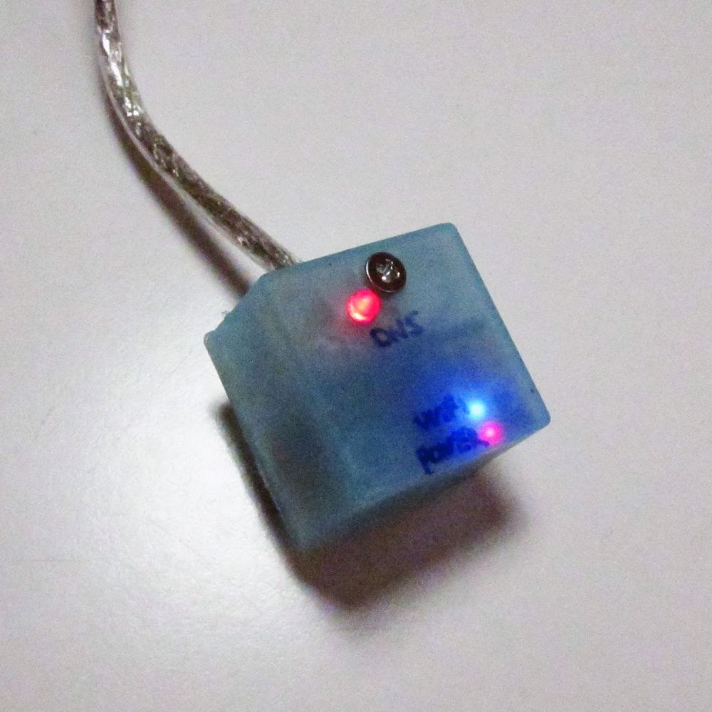
Summarizing it will be very simple, you just have to connect the router to a RS232 port, set the port at 115200 baud, no parity, 8bits and open your terminal software. Here you can the serial connection pins https://wiki.openwrt.org/_media/media/pirelli/alice-agpf.jpg, on the left the GND, top right RX, bottom right TX).
To enter the CFE prompt, you can press any key during the boot process, when the countdown stop message appears.
You have to run a TFTP server, to provide the firmware to your router.
I'm using tftpd32 (http://tftpd32.jounin.net/) and the Chaos Calmer 15.05.1 firmware (https://downloads.openwrt.org/chaos_calmer/15.05.1/brcm63xx/generic/openwrt-15.05.1-brcm63xx-generic-AGV2+W-squashfs-cfe.bin).
Just put the firmware in your tftpd32 folder, run the software and select the server interface to serve.
Supposing your interface is 192.168.1.120, on the CFE prompt you have to run the flashimage command as follow
> flashimage 192.168.1.120:openwrt-15.05.1-brcm63xx-generic-AGV2+W-squashfs-cfe.bin
This would load the firmware on your router.
The router will reboot, and you can now access the router by the 192.168.1.1 address on your web browser.
Note: if you would like to change your IP address using serial interface, just edit the network config file using the command
$vi /etc/config/network
You should change the ipaddr of the interface 'lan', also you can add your gateway and dns option here.


Now that you have a working OpenWrt device, we can setup it to provide the main WiFi access and a guest WiFi access.

Just open the Luci web interface of your OpenWrt, set your password and enable a SSH access to the main lan. The SSH access allows us to run configuration command throgh a SSH terminal.

Before going on we have to say that the WiFi board of this router does not support multiple SSID, so we have to use a USB adapater.
The following steps is needed only if your OpenWrt router does not supports multiple SSID and you have a RT72 driver compatible device, otherwise you must use your device proper driver.
I've a Ralink RT2501USB/RT2571W usb adapater, to make it work with at AGPF router we have to load the modules for USB and for the adapter.
We will do this by the opkg package system.
After the system reboot, to update the packages repository, we will run the command
$opkg update
We will install usbutils and the wireless tools, not closely needed but may be usefull
$opkg install usbutils
$opkg install wireless-tools
Now we are going to install USB modules
$opkg install kmod-usb-uhci
$opkg install kmod-usb2
A reboot is needed now.
We will install the Ralink RT2501USB/RT2571W (RT73) module
$opkg install kmod-rt73-usb
We will now reboot.
Now you should see a secondary WiFi on the Luci web interface.

We can now setup the first WiFi interface, and bind that to the lan network.
The DHCP must be disabled on the lan network to simulate an AP bridge behaviour.

We will make a new switch, that is new VLAN.
On VLAN 1, we disable port 2, 3 and 4, set 5 is untagged
On VLAN 2, we enable port 3, 5 is tagged
We are going to use port 3 as a wired guest port.
Note that the port 5 is the CPU, the physical port for port 3 is Eth4, port 2 Eth3.. and so on.
The untagged traffic will run on VLAN 1, the tagged one on VLAN 2.

Now we have to add guest firewall rules for guest interface.
This rule has to accept input, accept output, reject forward and Allow forward to destination zones -> lan, this way all the traffic will be forwared to lan.

The lan firewall rule must have enabled Masquerading and MSS clamping, it also have to Allow forward from source zones -> guest, to accept the forward traffic from guest, and Restrict Masquerading to all subnet but not the 192.168.1.0/24, by the value !192.168.1.0/24.

We can now add a guest interface, as bridge and add the VLAN 2 created on port 3.
We are going to set the guest interface with a static address, and enable DHCP for the guest interface assign the interface to the guest firewall zone.

Now we can set the guest WiFi, binding it to the guest interface.

Now we would have a primary WiFi over our main subnet 192.168.1.0/24, and a guest WiFi + a guest wired connection through port 3 of the router over our secondary subnet  192.168.2.0/24.

You can find below the main configuration files as example.

/etc/config/network
config interface 'loopback'
 option ifname 'lo'
 option proto 'static'
 option ipaddr '127.0.0.1'
 option netmask '255.0.0.0'

config globals 'globals'
 option ula_prefix 'fd6e:e9df:eb78::/48'

config interface 'lan'
 option ifname 'eth1'
 option force_link '1'
 option type 'bridge'
 option proto 'static'
 option ipaddr '192.168.1.3'
 option netmask '255.255.255.0'
 option ip6assign '60'
 option gateway '192.168.1.1'
 option dns '192.168.1.1'

config interface 'wan'
 option ifname 'eth0'
 option proto 'dhcp'

config interface 'wan6'
 option ifname 'eth0'
 option proto 'dhcpv6'

config switch
 option name 'eth1'
 option reset '1'
 option enable_vlan '1'

config switch_vlan
 option device 'eth1'
 option vlan '1'
 option ports '0 1 2 5'

config switch_vlan
 option device 'eth1'
 option vlan '2'
 option ports '3 5t'

config interface 'guest'
 option type 'bridge'
 option proto 'static'
 option ifname 'eth1.2'
 option ipaddr '192.168.2.1'
 option netmask '255.255.255.0'

/etc/config/firewall
config defaults
 option syn_flood '1'
 option input 'ACCEPT'
 option output 'ACCEPT'
 option forward 'REJECT'

config zone
 option name 'lan'
 option input 'ACCEPT'
 option output 'ACCEPT'
 option forward 'ACCEPT'
 option network 'lan'
 option masq '1'
 option mtu_fix '1'
 list masq_dest '!192.168.1.0/24'

config zone
 option name 'wan'
 option input 'REJECT'
 option output 'ACCEPT'
 option forward 'REJECT'
 option masq '1'
 option mtu_fix '1'
 option network 'wan wan6'

config forwarding
 option src 'lan'
 option dest 'wan'

config rule
 option name 'Allow-DHCP-Renew'
 option src 'wan'
 option proto 'udp'
 option dest_port '68'
 option target 'ACCEPT'
 option family 'ipv4'

config rule
 option name 'Allow-Ping'
 option src 'wan'
 option proto 'icmp'
 option icmp_type 'echo-request'
 option family 'ipv4'
 option target 'ACCEPT'

config rule
 option name 'Allow-IGMP'
 option src 'wan'
 option proto 'igmp'
 option family 'ipv4'
 option target 'ACCEPT'

config rule
 option name 'Allow-DHCPv6'
 option src 'wan'
 option proto 'udp'
 option src_ip 'fe80::/10'
 option src_port '547'
 option dest_ip 'fe80::/10'
 option dest_port '546'
 option family 'ipv6'
 option target 'ACCEPT'

config rule
 option name 'Allow-MLD'
 option src 'wan'
 option proto 'icmp'
 option src_ip 'fe80::/10'
 list icmp_type '130/0'
 list icmp_type '131/0'
 list icmp_type '132/0'
 list icmp_type '143/0'
 option family 'ipv6'
 option target 'ACCEPT'

config rule
 option name 'Allow-ICMPv6-Input'
 option src 'wan'
 option proto 'icmp'
 list icmp_type 'echo-request'
 list icmp_type 'echo-reply'
 list icmp_type 'destination-unreachable'
 list icmp_type 'packet-too-big'
 list icmp_type 'time-exceeded'
 list icmp_type 'bad-header'
 list icmp_type 'unknown-header-type'
 list icmp_type 'router-solicitation'
 list icmp_type 'neighbour-solicitation'
 list icmp_type 'router-advertisement'
 list icmp_type 'neighbour-advertisement'
 option limit '1000/sec'
 option family 'ipv6'
 option target 'ACCEPT'

config rule
 option name 'Allow-ICMPv6-Forward'
 option src 'wan'
 option dest '*'
 option proto 'icmp'
 list icmp_type 'echo-request'
 list icmp_type 'echo-reply'
 list icmp_type 'destination-unreachable'
 list icmp_type 'packet-too-big'
 list icmp_type 'time-exceeded'
 list icmp_type 'bad-header'
 list icmp_type 'unknown-header-type'
 option limit '1000/sec'
 option family 'ipv6'
 option target 'ACCEPT'

config include
 option path '/etc/firewall.user'

config rule
 option src 'wan'
 option dest 'lan'
 option proto 'esp'
 option target 'ACCEPT'

config rule
 option src 'wan'
 option dest 'lan'
 option dest_port '500'
 option proto 'udp'
 option target 'ACCEPT'

config zone
 option input 'ACCEPT'
 option forward 'REJECT'
 option output 'ACCEPT'
 option name 'guest'
 option network 'guest'

config forwarding
 option dest 'lan'
 option src 'guest'

/etc/config/wireless
config wifi-device 'radio0'
 option type 'mac80211'
 option hwmode '11g'
 option path 'pci0000:00/0000:00:01.0/ssb0:0'
 option channel '1'
 option txpower '20'
 option country 'IT'

config wifi-iface
 option device 'radio0'
 option mode 'ap'
 option network 'lan'
 option encryption 'none'
 option ssid 'OpenWrt'

config wifi-device 'radio1'
 option type 'mac80211'
 option channel '11'
 option hwmode '11g'
 option path 'platform/ehci-platform/usb1/1-1/1-1:1.0'
 option txpower '20'
 option country 'IT'

config wifi-iface
 option device 'radio1'
 option mode 'ap'
 option ssid 'OpenWrtGuest'
 option network 'guest'
 option encryption 'none' 

/etc/config/dhcp
config dnsmasq
 option domainneeded '1'
 option boguspriv '1'
 option filterwin2k '0'
 option localise_queries '1'
 option rebind_protection '1'
 option rebind_localhost '1'
 option local '/lan/'
 option domain 'lan'
 option expandhosts '1'
 option nonegcache '0'
 option authoritative '1'
 option readethers '1'
 option leasefile '/tmp/dhcp.leases'
 option resolvfile '/tmp/resolv.conf.auto'
 option localservice '1'

config dhcp 'lan'
 option interface 'lan'
 option dhcpv6 'server'
 option ra 'server'
 option ignore '1'
 option ra_management '1'

config dhcp 'wan'
 option interface 'wan'
 option ignore '1'

config odhcpd 'odhcpd'
 option maindhcp '0'
 option leasefile '/tmp/hosts/odhcpd'
 option leasetrigger '/usr/sbin/odhcpd-update'

config dhcp 'guest'
 option start '100'
 option leasetime '12h'
 option limit '150'
 option interface 'guest' 


Notes
  • read risk disclaimer
  • excuse my bad english

Saturday, August 5, 2017

MQ gas sensor correlation coefficients

I've have talk about MQ sensors here:
http://davidegironi.blogspot.it/2017/05/mq-gas-sensor-correlation-function.html

In the post linked above I've discuss a method to correlate the sensor resistance to a gas ppm using the datasheet curve named "sensitivity characteristics of the MQ-135" and the formula:
ppm=a*(Rs/Ro)^b.
Someone ask me about sensor and correlation coefficients of various gasses, so here I will post some correlation coefficient for the a few MQ sensor and gasses.

sensor gas a b min Rs/Ro max Rs/Ro
MQ2 LPG 591.283 -2.076502 0.256166 1.68543
MQ3 alcohol 0.3923202 -1.493249 0.1143375 2.497754
MQ4 CH4 1041.333 -2.729007 0.4365277 1.830508
MQ5 CH4 217.4972 -2.422111 0.2058715 1.035233
MQ6 LPG 940.2178 -2.521573 0.3915661 1.847477
MQ7 H2 64.86522 -1.405261 0.05323301 1.203488
MQ8 H2 1079.683 -0.6416874 0.03115283 13.84067
MQ135 CO2 110.3794 -2.721706 0.8038119 2.416431

Those values have been found using the method proposed in the above post, and the figures posted below.
In order to use the correlation function, you now need to compute the Ro value. You can find this value reading the sensor resistance at a know amount of ppm, compy in the gases ppm limits of the datasheet, and then use this formula:
Ro=Rs*(a/ppm)^(1/b).

Those are the
 - collected points: https://bitbucket.org/snippets/davidegironi/z9AMEr/mq-gas-sensor-correlation-coefficients
that has been processes using the following
 - R script: https://gist.github.com/davidegironi/b7be6b7cace6b475dd42c48c3e62fcf4


Notes
  • read risk disclaimer
  • excuse my bad english

Sunday, July 2, 2017

MQ gas sensor correlation function against temperature and humidity

We have taken a look at the MQ sersor in this post here:
As I said those sensor are electro-chemical. Accuracy of those sensor is not the best. Also they will react to many gases. It means that if you are trying to measure the ppm of a certain gas with this sensor, you will have false measurement values if any of the other gas that the sensor react to, changes.
Here I will "overengeneer" on this type of sensor, trying to correlate the MQ sensor readings to temperature and humidity too, even if this correlation to me is not prominent. The correlation formula I've found may be wrong, so let me know if there is something to fix here.

As the previous post, let's consider the MQ-135 sensor as reference, find below the "sensitivity characteristics of the MQ-135" figure of the datasheet we used to obtain ppm from resistance redings.


The MQ sensor datasheet also comes with a "typical dependence curve of the sensor on temperature and humidity" let's call it dependance curve.


It shows us how the Rs/Ro change against temperature and humidity.

What we are searching here, it's a way to relate the sensitivity characteristics curve with the temperature and humidity dependance curve.
It means, a way to find out ppm, reading the sensor resistance at any given temperature and humidity. 

Before going ahead.
Notice that the sensitivity characteristics curve, from which we have found the correlation function ppm=a*(Rs/Ro)^b coefficients a and b, it's acquired under certain circumstances, as example for the MQ-135 sensor 20C temperature, 65% humidity, O2 21%, Rl 20k, Ro at 100ppm of NH3 in the clean air.

The dependance curve of the sensor also it's acquired under certain circumstances, as example for the MQ-135 sensor Rs at 100ppm of NH3, Ro at 100ppm of NH3 in air at 33%RH and 20C.

At first we have to ask if we can relate sensitivity characteristics curve to dependance curve of the sensor?
Each curve it's taken under different circumstances, the first has both Rs and Ro acquired at 20C temperature, 65% humidity, the second one has Ro acquired at 20C temperature, 33% humidity. Both ratio related to a Ro at 100ppm of NH3.
The Ro of the sensitivity characteristics curve it's taken at Ro at 100ppm of NH3 in clean air, just as the Ro of the dependance curve, only temperature and humidity differs. Obviously it means that the sensor resistance at 100ppm of NH3 Rs it's just Ro, at any temperature and humidity,
This does not means that the sensitivity characteristics curve it's valid under any temperature and humidity, notice that the dependance curve may differs under different gas concentration, or different gas. We just know it's acquired for 100ppm of NH3, but we do not know what's the dependance curve at other gas concentration. Also the sensitivity characteristics curve may differs under different circumnstances of temperature and humidity.
If we suppose that the dependance curve it's linear over different gases and concentration, we may relate the ratio of the sensitivity characteristics curve to dependance curve.

We get the a and b coefficients for the correlation function ppm=a*(Rs/Ro)^b from the sensitivity characteristics curve.
To estimate the Ro, we read the sensor resistance at temperature T1 and humidity H1 (Rs_T1CH1%) given a know amount of gas to estimate. We are trying to estimate Ro at 100ppm of NH3, at temperature 20C and humidity 65% (Ro_20C65%).
Ro_20C65%=Rs_T1CH1%*(a/ppm)^(1/b)
Because the sensitivity characteristics curve it's acquired 20C and 65%, we need to correlate Rs_T1CH1% to Rs_20C65%. We can do this, because we have assumed that the dependance curve it's linear over different gas amount.
Defined Ro at 100ppm of NH3 20C and 33% as Ro_20C33%, by the dependance curve
Rs_T1CH1% / Ro_20C33% = m
and
Rs_20C65% / Ro_20C33% = n
so
Rs_20C65% = (n / m)*Rs_T1CH1%
and
Ro_20C65%=(n / m)*Rs_T1CH1%*(a/ppm)^(1/b)

Now conditions changed, we are at temperature T2 C and humidity H2 % (Rs_T2CH2%).
So hour function is not yet valid
ppm=a*(Rs_T2CH2%/Rs_20C65%)^b
for this function to be validated, we need the to correlate Rs at temperature T2 C and humidity H2 % (Rs_T2CH2%) to temperature 20C and humidity 65% (Rs_20C65%).
As we does for the previos correlation
Rs_T2CH2% / Ro_20C33% = t
and
Rs_20C65% / Ro_20C33% = q
so
Rs_20C65% = (q / t)*Rs_T1CH1%
and
ppm=a*((q*Rs_T1CH1%)/(t * Rs_20C65%))^b

To find out the correlation factor between this ratio, the simpler thing here, is to build up two lookup tables, one for each of the curves showed.
On the MQ-135 we will get a lookup table for 85%RH and one for 33%TH curve.
We can do this by using a tool like WebPlotDigitalizer.
Now, we have two lookup table, for two different humidity values. Each of the points of that lookup tables represent the Rs/Ro against a certain temperature.

lookup_33 = (t_1C33%, RsRo_1C33%),  (t_2C33%, RsRo_2C33%) ... (t_nC33%, RsRo_nC33%) 
lookup_85 = (t_1C85%, RsRo_1C85%),  (t_2C85%, RsRo_2C85%) ... (t_nC85%, RsRo_nC85%)

We can use linear interpolation (https://en.wikipedia.org/wiki/Linear_interpolation) to relate Rs/Ro to any temperature and humidity.

As example, suppose we have read Rs at 22C, 50%
Rs_22C50%/Ro_20C33% will be the interpolation between Rs_22C33%/Ro_20C33% and Rs_22C85%/Ro_20C33%.
Rs_22C33%/Ro_20C33% = RsRo_20C33% + (22C - 20C)*(RsRo_30C33% - RsRo_20C33%)/(30C-20C)
Rs_22C85%/Ro_20C33% = RsRo_20C85% + (22C - 20C)*(RsRo_30C85% - RsRo_20C85%)/(30C-20C)
Rs_22C50%/Ro_20C33% = RsRo_22C33% + (50% - 33%)*(RsRo_22C85% - RsRo_22C33%)/(85%-33%)

At the end it's just a matter of linear interpolation, to find out m and n values to estimate Ro at 100ppm NH2 temperature 20C and 65% humidity, and t and q values to estimate Rs at temperature 20C and 65% humidity.

All have been implemented and tested using an ATmega8.
The underlying chart shows the CO2 ppm correlation.
Time is reported on the x-axis, CO2 ppm values on the left y-axis, humidiy and temperature values on the right y-axis.
The MQ135 resistance reading are then translated to ppm with and without the temperature / humidity correlation method (green lines).
A reference NDIR sensor shows us an accurate CO2 reading.
As you can see the CO2 temperature/humidity correlation function works slightly better than the uncorrelated one.
Tests are repeated 3 times per sensor, using 3 MQ135 sensors.


The code below implements the resistance to ppm corrleation functions, and also the temperature and humidity correlation functions, as the main correlation function mq_getppmtemphumd.


Code


Notes
  • read risk disclaimer
  • excuse my bad english

Monday, June 5, 2017

vSphere ESXi backup strategies for lowering power consumption

For my home development servers I use the vSphere ESXi 6.5 hypervisor.


At home I do not need all the virtual machines on that server to be online 24/24 365/365, so this server is not always powered on. I need strategies to power up this server on needs.
That was achived by using the Wake on LAN (WoL).
I enable WOL on BIOS of that PC, so I can start the server whenever I need using the poweroff.exe utility (http://users.telenet.be/jbosman/applications.html) and a small batch file that simply launch poweroff.
Let's suppose my server has the IP 192.168.1.10 and mac 010203040506 the command below should start the server:
poweroff.exe wol -ip 192.168.1.10 -subnet 255.255.255.0 -mac 010203040506

Then I need something to backup virtual machines on that hypervisor, I build a bounch of script to perform the backup strategy I need.

But at first, let's talk about the hypervisor and the hardware used.
I was using ESXi since 5.0, this year I switch from 5.5 to 6.5.
My main server it's a HP Compaq dx2400 microtower powered by a Xeon E5440 and 8Gb RAM, the hypervisor is intalled on a 32Gb USB flash drive and hosts on a 1Tb HDD. It uses almost 60W.
This PC comes out with a Core 2 Due processor, but I've upgraded it to a Xeon E5440, due to the simplicity of the operation. A note about this upgrade, the Xeon processor I've used comes from a chinese seller already modded for the LGA 775 socket, also the latest BIOS for the motherboard of this PC (5.37 Rev.) does support the Xeon E5440.
I just need to install the new Xeon CPU, reset the BIOS, and power it up. Then I've enabled VT on bios.
For further information on this mod, search for LGA 771 to 775 adapter mod. To be sure my motherboard supports this CPU I've used the intelmicrocodelist.exe tool to look at the CPU supported by my motherboard BIOS.

I would like to backup each virtual machine on a remote disk. I've done this mounting a NFS disk on the ESXi.
The NFS service and disk is provided by a Netgear Stora NAS.
On that NAS i enabled NFS by kernel mode, If you've fot a Netgear Stora you can find further information here: http://www.openstora.com/wiki/index.php?title=Kernel_mode_NFS.
I use a Samba shared folder as main NFS entry point, in order to simply the backups download and look at all the files. My NFS entry in /etc/exports map the NFS user to the main stora user, that way by the share I can eventually delete files. On NFS this is authorized by the all_squash option. Let's suppose my store username is yourusername, the NFS folder is /home/yourusername/folder and yourusername id and group id are 10 and 11 (use the folling commands to get a username and group id on linux $id -u yourusername and $id -g yourusername).
My /etc/export entry looks like this:
/home/yourusername/folder 192.168.1.0/255.255.255.0(rw,sync,all_squash,anonuid=10,anongid=11,no_subtree_check)
As a side note, that Netgear Stora NAS is also modded to mount two disk wihout raid. I use one of the disk for PCs backup and the other one for ESXi backups.

Now, let's came to the backups.
I've chosen ghettoVCB script (https://github.com/lamw/ghettoVCB) as my backup engine because it's simple, opensource, and well documented.
ghettoVBS is is installed using instructions from the ghettoVCB page. This are the basic steps:
Download the ghettoVCB offline bundle to tmp folder and run
$esxcli software vib install -d /vghetto-ghettoVCB-offline-bundle.zip -f
Mount a NFS datastore on the hypervisor (ex backups01)
Make a ghettoVCB folder in the backup datastore (or other one)
$mkdir /vmfs/volumes/backups01/ghettovcb
Copy ghettoVCB.conf to the folder created
$cp /etc/ghettovcb/ghettoVCB.conf /vmfs/volumes/backups01/ghettovcb/ghettoVCB.conf
Edit ghettoVCB.conf at least set the backup folder
  VM_BACKUP_VOLUME=/vmfs/volumes/backups01
and the backup rotation count
  VM_BACKUP_ROTATION_COUNT=2

The backup strategy I've implemented is simple.
I run ghettoVCB each week to perform a full backup of each virtual machine, ghettoVCB handles the backups rotation. In order to lowering power consumption (remember that this server is not always on) I've implement this simple strategy, running a script at the the boot stage the hypervisor, This script:
  1. adds ghettoVCB crontab for day N of week time HH:MM+20min
  2. check if the hypervistor is switched on "next to" day N of week time HH:MM, if so
    • add a shutdown trigger file (the shutdown operation only runs if exists a shutdown trigger file)
    • add crontab for shutdown the server after H hours
An external device sends a WOL packet at day N of week time HH:MM-10min, if the hypervisor it is switched on at that time nothing happens, if not it will power up, schedule the ghettoVCB backup and eventually power down after the backups end.
The shutdown trigger file it is usefull to interrupt the shutdown procedure. Imagine that one want the server to stay on, he just has to delete the shutdown trigger file, available on the NFS Samba shared folder of backups.
This is all packed in the backuphelper.sh file you can find here https://gist.github.com/davidegironi/73f7dc8c65625d51b9a45e9fbe2f73c2
To use the backuphelper, you have to make a backuphelper folded
$mkdir /vmfs/volumes/backups01/backuphelper
Copy backuphelper.sh and esxidown.sh to the folder created
$cp /tmp/backuphelper.sh /vmfs/volumes/backups01/backuphelper/backuphelper.sh
$cp /tmp/esxidown.sh /vmfs/volumes/backups01/backuphelper/esxidown.sh
Edit backuphelper.sh setting the running parameters at top of file
Run backuphelper.sh at startup, edit file /etc/rc.local.d/local.sh adding commands below
  /vmfs/volumes/backups01/backuphelper/backuphelper.sh S

This backuphelper uses the esxidown script (https://github.com/sixdimensionalarray/esxidown) to gently shutdown the hypervisor.

The external device I'm using to send the WOL packet is a D-Link DSL-2750B/DSL-2751 rev D1 with OpenWrt installed, which I'm using as the main DHCP/DNS server in my home network. On this OpenWrt the etherwake package is installed, the etherwake command for WOL is set as a Scheduled Task.
Let's suppose my server mac is 010203040506 and I want to switch the server on on day 6 at 2:10 using the eth0.1 port, the command will look like this:
10 2 * * 6 /usr/bin/etherwake -D -i "eth0.1" "01:02:03:04:05:06"
Also, if you would like to make a backup, let's say the first saturday of month, the crontab schedule will look like:
10 2 1-7 *   *  [ "$(date '+%a')" = "Sat" ] && /usr/bin/etherwake -D -i "eth0.1" "01:02:03:04:05:06"

Another thing to take in consideration is the timezone, and time accuracy, all my devices have the NTP client enabled, and all the timezone are UTC.


Notes
  • read risk disclaimer
  • excuse my bad english

Monday, May 1, 2017

MQ gas sensor correlation function estimation by datasheet


The MQ series are cheap gas sensors.
They are resistive electro-chemical sensors.
These sensors have a heating element and a resistance that react to gases.
Below a MQ135 sensor opened. Inside it looks like that.


To read the sensor's resistance, we measure the voltage drop of the sensor.
The method we use to measure resistance on the micro is by using the ADC, and a pull-up (or pull-down) resistor. Here http://electronics.stackexchange.com/a/70012 you can find a good explanation on the pull-down/up method on reading resistance.

Some people are asking me in my previous post about the MQ135 sensor, http://davidegironi.blogspot.it/2014/01/cheap-co2-meter-using-mq135-sensor-with.html how to obtain correlation function for other MQ series sensor, or other gas.

In this post I will explain a simple (to me) method of obtaining correlation function for any MQ series sensors that fit an exponential function.

An italian version of this article has been published in the may number of Elettronica In (http://www.elettronicain.it/) magazine.


As a reference, let's consider the MQ135 sensor (again).
We will look at the "sensitivity characteristics of the MQ-135" figure of the datasheet.


Notice that it's a log-log plot, this means that is has logarithmic scales on both axes.
Another thing to notice, is that the y-axis is for Rs/Ro, it will be much clearer if we impose ppm on the y-axis.
So as a first step, we will flip the axis.
As a reference, above we will see a flip axis example


Now, let's take a look at a power function with different exponents.


Let's try to plot those function on a log-log scale.


You may notice that an exponential function flipped is again an exponential function, with different coefficient of course.
As you may see, the power function with a negative exponent looks like the one we are searching for.
Summarizing, let's take the power function y=x^-2 and plot this on the log-log scale, with a 10 multiplier


We are searching for something like:

y=a*x^b

with b<0

Now, our purpose is to find out the value of the and b constants, starting from the datasheet figure.
We can do this by performing a nonlinear regression. Specifically we need a power regression.
First, we need to collect values from the datasheet figure.
WebPlotDigitizer is the tool we are going to use here: https://github.com/ankitrohatgi/WebPlotDigitizer. We can find few online tutorials that teach us how to use WePlotDigitalizer. I will try here to sum it up here:
1) extract the figure from the datasheet
2) load the figure on WebPlotDigitalizer
3) set axis, remember to se axis both as log
4) check out points from the curve of the gas you need to found
5) click on the view data button, and you get the points you need.

Now that we have found out the points of the curve from the datasheet, we need something to load with those points and perform a power regression.
You can use matlab or you favorite math software tools. There are also other online tools you can use to perform power regressions. Here I will use an R (ref. https://en.wikipedia.org/wiki/R_(programming_language)) script I've write.

You just have to load the points values you have found out, and launch this R script. You can also launch it on http://www.r-fiddle.org/.
The script will find out the function coefficients (a and b), and print out the function found next to the graph points, just to check the function's accuracy.

Below the Rs/Ro vs ppm function, as seen on the datasheet.


Then the flipped function we are searching for


Then, the plot of both functions on linear scale axes:


Now we have to estimate the Ro coefficient.
Ro estimation is quite simple
We just need to solve this equation for Ro
ppm=a*(Rs/Ro)^b
Ro=Rs* sqrt(a/ppm,b)=Rs*(a/ppm)^(1/b)
note: in my library here: http://davidegironi.blogspot.it/2014/01/cheap-co2-meter-using-mq135-sensor-with.html i simply Ro as Rs*sqrt(a/ppm,b) = Rs*exp(ln(a/ppm)/b), which is the same that Rs*(a/ppm)^b.

So given the function coefficients, we have to measure the resistance of the sensor at a know amount of ppm for the gas we are investigating.

Now, just substitute the found function coefficients (a and b), the resisteance we have read (Rs in ohm) at the amount of gas (ppm) to the estimation Ro function
Ro=Rs*(a/ppm)^b

One last step is to provide the Rs/Ro limits we are going to use to validate the input for our solving function ppm=a*(Rs/Ro)^b
We know that Rs/Ro=(ppm/a)^(1/b)
So
min[Rs/Ro]=(max[ppm]/a)^(1/b)
max[Rs/Ro]=(min[ppm]/a)^(1/b)
By the datasheet figure we have to select the max and min Rs/Ro and ppm points.
Notice that we get the max Rs/Ro value for the min ppm point value.

Here you can find the R script to estimate correlation function coefficients, compute Ro, min and max Rs/Ro (input: x/y axis limits, correlation function points, resistance of the sensor in ohm at a know amount of gas in ppm).
On gist: https://gist.github.com/davidegironi/b7be6b7cace6b475dd42c48c3e62fcf4

Above an implementation of the raw value to ppm conversion, sample sketch for Arduino:

//sensor input PIN
int mqInput = A1;
//pull-down resistor value
int mqR = 22000;
//rO sensor value
long rO = 41763;
//min value for Rs/Ro
float minRsRo = 0.358;
//max value for Rs/Ro
float maxRsRo = 2.428;
//sensor a coefficient value
float a = 116.6020682;
//sensor b coefficient value
float b = -2.769034857;

void setup() {
  pinMode(mqInput, INPUT);
  Serial.begin(9600);
}

void loop() {
  int adcRaw = analogRead(mqInput);
  long rS = ((1024.0 * mqR) / adcRaw) - mqR;
  Serial.print("Rs: ");
  Serial.println(rS);
  float rSrO = (float)rS / (float)rO;
  Serial.print("Rs/Ro: ");
  Serial.println(rSrO);
  if(rSrO < maxRsRo && rSrO > minRsRo) {
 float ppm = a * pow((float)rS / (float)rO, b);
 Serial.print("ppm: ");
 Serial.println(ppm);
  } else {
 Serial.println("Out of range.");
  }
  delay(1000);
}

You can find the temperature and humidity correlation function here: http://davidegironi.blogspot.com/2017/07/mq-gas-sensor-correlation-function.html

Notes
  • read risk disclaimer
  • excuse my bad english

Sunday, April 2, 2017

An AVR ATmega R/C control signal reader - Method/01


The Radio Control (R/C or RC) is the method of controlling remote devices using radio frequencies.
Most of the time the RC signal uses RC servo signals.
Servo signal is a square PWM signal, usually with a period of 20ms and a duty time between 1ms and 2ms. More info on the wikipedia page here: https://en.wikipedia.org/wiki/Servo_control.


This library implements a method to read an RC signal and eventually map this to a 0..100 number.

It's developed on an ATmega8 running at 16Mhz.
It makes use of the external interrupt PIN and a timer to count the duty period time.
It's customizable to fit the user preferences. Configuration can be found in rcin1.h header file.
Theory of operation: each time a rising edge interrupt it is raised, a timer starts counting until the falling edge happens. Then the number of ticks counted between interrupts is transformed to us spent in duty time.
Input PIN is INT0.
The RC signal it is measured and then mapped to a speed value from 0 to 100.


Code
Notes
  • read risk disclaimer
  • excuse my bad english

Wednesday, March 1, 2017

An Arduino Knight Rider Rainbow dice that uses WS2812B RGB leds


This project implements a Knight Rider / Rainbow effect Random Selector.
It uses an Arduino UNO and a WS2812B RGB led strip.
A friend of mine needs a random selector for train scale model.
I've developed this using the Arduino framework, because he would like to modify the sketch "the Arduino way".
Unluckly I have not any picture or video of his build. So I've built a dice selector by using an old clock frame. I would like to thank my friend Matteo for cutting vinyls out for this project.


This project uses the Adafruit "NeoPixel library" (https://github.com/adafruit/Adafruit_NeoPixel).
For the Knight Rider Rainbow effect I took inspiration from the technobly "NeoPixel Knight Rider" project (https://github.com/technobly/NeoPixel-KnightRider).
The circuit for this project is really simple, there is just a Start switch connected, and a WS2812B led strip.


When the user press the start switch, the  Knight Rider / Rainbow selector starts, and a semi-randomic led is choses.
After a while, a Rainbow effect starts powering on all the leds.


Code

Notes
  • read risk disclaimer
  • excuse my bad english

Saturday, February 4, 2017

Duck DNS ESP8266 mini WiFi client


This is a Duck DNS ESP8266 mini WiFi client.


Duck DNS (https://www.duckdns.org/) is a free Dynamic DNS (DDNS) service.
It as a few client available for many operating system and a few routers.
A friend of mine runs a router that does not support any of the Duck DNS update mode. Instead of loading his operating system with the Duck DNS updater, or installing an openwrt router, I've implemented an ESP8266 client.


It is powered by USB, it can also be powered by the router USB port.
It's built on a pretty old ESP-01 board.
It has two led, one is the ESP-01 WiFi connection status embedded one, the other is connected to the GPIO2 port, and it's used for the DNS update status.


We need just a 3.3 voltage regulator to run this board using any 5V USB power output capable of 200mA.
The code is written using the Arduino IDE + ESP8266 core, to me that's the fastest and simple way to work with ESP8266.

The WiFiManager library (https://github.com/tzapu/WiFiManager) is used to facilitate the WiFi connection of this module.

Also it runs a web server that allow any user to setup the DuckDNS connection parameters.
User can set the DDNS domain name and token, and also the update interval and the module hostname, that way one can just forget the module IP and open the web configuration page by board name. The default board name is espduckdns001, so the web page address is http://espduckdns001


Code

Notes
  • read risk disclaimer
  • excuse my bad english