
A pickup winding machine it is used to wind a guitar pickup.
You can find my previous ATmega manual pickup winding machine here: http://davidegironi.blogspot.it/2014/05/a-pickup-winding-machine-built-on.html
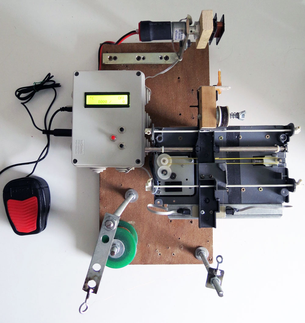
This project is a manual / CNC pickup winding machine, built on top of an ATmega8 microcontroller.
Characteristics:
- wind counter
- slow startup
- automatic stop
- configurable motor speed
- configurable winds
- 2 direction
- CNC automation
- configurable wire dimension (for CNC)
- traverse dynamic speed
- the current motor direction
- the rotating speed of your pickup
- the total and current wind counter
- the direction of the traverse mechanism
- the speed of the traverse motor
There are 3 buttons, SELECT, button UP and DOWN.
Short press SELECT to move to make the traverse motor move 1mm.
Long press SELECT to enter / exit programming mode. During the programming mode press button UP and DOWN to edit the selected value, short press SELECT to skip the next value, or long press SELECT to save new values and go back to running mode.
Short press button UP to change direction of the winding.
Long press button UP to reset counter.
Short press button UP to change direction of the guide movement.
Long press button DOWN to reset counter.

If you are in building mode, to make the wind start press the RUN pedal, it will start with a slow startup, to stop the winder release the RUN pedal.
The winding machine will automatically stops when the wind counter reach the configured number.
If you disable the autostop mode, the machine will always count wind, independently by the direction choosen.
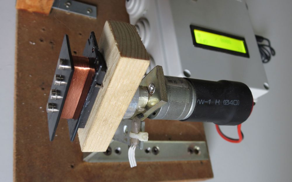
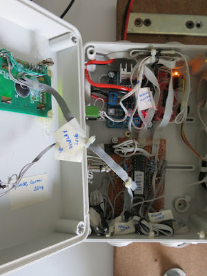
The winding motor used is cheap DC motor 12V 1200rpm, the motor driver is L298N chip board.
The traverse mechanism it is built using parts from a (broken) scanner, the guide motor is the stepper motor of the scanner.

Traverse mechanism has two limits. Limits are build using break-beam optosensos mounted on a small cilindric neodymium magnet.
That way guide limits can be moved depending on the pickup to be wired.
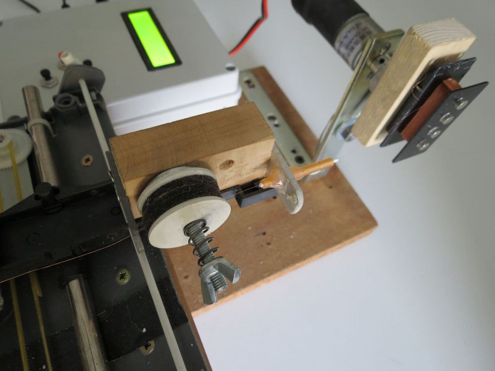
The wire tensioner it build using felts and a spring. It is simple but it works quite good.
The winding nozzle it's taken apart from a dental saliva ejector that my father (who is a dentist), gives me. It has a really small hole, and it's also built with plastic. This will not damage the wire we are going to wind.
The counter sensor it is built using a hall effect switch and a small neodymium magnet glued to the pickup holder.
Whenever the guide mechanism is changed, those constants has to be set GUIDEMOTOR_1STEPUM, GUIDEMOTOR_1MMSTEP, GUIDEMOTOR_1CMMAXSPEEDTIMEMS, GUIDEMOTOR_1CMMINSPEEDTIMEMS, GUIDEMOTOR_FIXEDSPEED_DEFAULT, WIRE_MINGAUGE, WIRE_MAXGAUGE
There are two calibration steps the user has to do:
- Measure the traverse distance moved per step. The GUIDEMOTOR_MEASURESTEP directive has to be set to 1, and the number of step to move has to be set in GUIDEMOTOR_MEASURESTEPSTEPS. Then the hex has to be compiled and uploaded. Now when you startup the machine, the guide will move for the desired number of steps. We measure the distance traveled. We compute the steps/mm as steps moved / total distance traveled. Than um/step is 1000 / steps/mm. Let's suppose we have set 20000 as step to move. If we have measured a traveled distance of 106mm, the step/mm is 188.879, and um/step is 1000/188.879, so 5.29. When done, set GUIDEMOTOR_MEASURESTEP to 0 again. Now we can set GUIDEMOTOR_1MMSTEP to step/mm value and GUIDEMOTOR_1STEPUM to um/step value.
- Measure the traverse maximum / minimum speed. The GUIDEMOTOR_MEASURESPEED directive has to be set to 1. Then the hex has to be compiled and uploaded. Now when you startup the machine, the LCD will show the max and min speed the guide motor takes to move 1cm. When done, set GUIDEMOTOR_MEASURESPEED to 0 again. Now we can set GUIDEMOTOR_1CMMAXSPEEDTIMEMS and GUIDEMOTOR_1CMMINSPEEDTIMEMS to the values shown on the display.
A guide step helper spreadsheet it is provided to help compute that values. The GUIDEMOTOR_FIXEDSPEED_DEFAULT, WIRE_MINGAUGE and WIRE_MAXGAUGE dimensions can be computed using this sheet.
You just has to fill values you already know, the values of your hardware.
You just has to fill values you already know, the values of your hardware.
The math to compute that values is also described as comments in the source files.
The maximum and minimum wire gauge it is an important parameter that defines what your pickup winder can wrap.
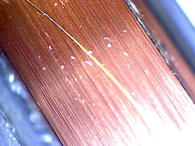
The winding pattern implement in this machine, is a simple traverse winding that places each wire wind next to the previous one.
See below and example of a pickup winded with this machine.
Things get's intereseting here, because the wiring motor doesn't always spin the same speed, take as example the "slow startup" stage, or when you decide to wire your pickup at a lower speed.
The guide motor is driven in a TIMER interrupt.
Here we set the steps that motor walk to position the cable,
We know:
We can compute how much space the traverse mechanism has to travel in order to place the wire next to the previus one, that's pretty simple.
number_of_winds = current_number_of_winds - current_number_of_winds
distance_to_wire = wire_gauge * number_of_winds
step_to_move = distance_to_wire / guide_motor_distance_traveled_for_1_step
Things get's a little complicated because i'm not using float math, so i've to record the remnant of the division.
number_of_winds =
current_number_of_winds - current_number_of_winds
distance(um)_to_wire =
wire_gauge(um) * number_of_winds + remntant_distance(um)_to_wire
step_to_move =
distance(um)_to_wire / guide_motor_distance(um)_traveled_for_1_step
remntant_distance(um)_to_wire =
distance(um)_to_wire % guide_motor_distance(um)_traveled_for_1_step
But that's not all folks, we also have to move the guide motor at such a speed that every wire is placed next to the other right when the pickup has done a full loop, I mean, we do not want a rapid guide motor travel, then a motor stop, then a rapid travel again, that movement has to be continous, and smooth, related to the pickup winding speed.
So, let's try to estimate that guide motor speed.
rotation_per_seconds = motor_rpm / 60
distance(um)_to_wire_in_1second = rotation_per_seconds * wire_gauge(um);
time(ms)_to_wire_1cm = (10000*1000) / distance(um)_to_wire_in_1second;
Now, the trick here it that we have previously recorded the maximum and minimum time in ms that the guide motor takes to move 1cm, so we can map the time we need, with that max and min speed.
speed = 100 - (time(ms)_to_wire_1cm - GUIDEMOTOR_1CMMAXSPEEDTIMEMS) * (100 - 1) / (GUIDEMOTOR_1CMMINSPEEDTIMEMS - GUIDEMOTOR_1CMMAXSPEEDTIMEMS) + 1;
That way we obtain a speed value from 1 to 100 for the guide motor to run smooth.
Enabling GUIDEMOTOR_DEBUGSTEPANDSPEED will display the current speed and steps left to run for the guide motor. This is a usefull during the debug stage. The speed will never exceed 100, and the steps left will never grow up. It it happens, it means that the guide is going too slow.

Future improvements will be implement an UART protocol to drive this machine by a PC, that way multiple wiring pattern can be simply performed.
This project was developed on Eclipse, built with avr-gcc on ATmega8 @ 16MHz.
Code
Notes
The maximum and minimum wire gauge it is an important parameter that defines what your pickup winder can wrap.
The winding pattern implement in this machine, is a simple traverse winding that places each wire wind next to the previous one.
See below and example of a pickup winded with this machine.

Things get's intereseting here, because the wiring motor doesn't always spin the same speed, take as example the "slow startup" stage, or when you decide to wire your pickup at a lower speed.
The guide motor is driven in a TIMER interrupt.
Here we set the steps that motor walk to position the cable,
We know:
- the number winds made from the last motor movement
- the current pickup rotation speed
- the wire gauge
- how many distance the guide motor travel for every step done
- the maximum and minimum time the guide motor takes to walk 1cm

We can compute how much space the traverse mechanism has to travel in order to place the wire next to the previus one, that's pretty simple.
number_of_winds = current_number_of_winds - current_number_of_winds
distance_to_wire = wire_gauge * number_of_winds
step_to_move = distance_to_wire / guide_motor_distance_traveled_for_1_step
number_of_winds =
current_number_of_winds - current_number_of_winds
distance(um)_to_wire =
wire_gauge(um) * number_of_winds + remntant_distance(um)_to_wire
step_to_move =
distance(um)_to_wire / guide_motor_distance(um)_traveled_for_1_step
remntant_distance(um)_to_wire =
distance(um)_to_wire % guide_motor_distance(um)_traveled_for_1_step
So, let's try to estimate that guide motor speed.
rotation_per_seconds = motor_rpm / 60
distance(um)_to_wire_in_1second = rotation_per_seconds * wire_gauge(um);
time(ms)_to_wire_1cm = (10000*1000) / distance(um)_to_wire_in_1second;
Now, the trick here it that we have previously recorded the maximum and minimum time in ms that the guide motor takes to move 1cm, so we can map the time we need, with that max and min speed.
speed = 100 - (time(ms)_to_wire_1cm - GUIDEMOTOR_1CMMAXSPEEDTIMEMS) * (100 - 1) / (GUIDEMOTOR_1CMMINSPEEDTIMEMS - GUIDEMOTOR_1CMMAXSPEEDTIMEMS) + 1;
That way we obtain a speed value from 1 to 100 for the guide motor to run smooth.
Enabling GUIDEMOTOR_DEBUGSTEPANDSPEED will display the current speed and steps left to run for the guide motor. This is a usefull during the debug stage. The speed will never exceed 100, and the steps left will never grow up. It it happens, it means that the guide is going too slow.

Future improvements will be implement an UART protocol to drive this machine by a PC, that way multiple wiring pattern can be simply performed.
This project was developed on Eclipse, built with avr-gcc on ATmega8 @ 16MHz.
Code
Notes
- read risk disclaimer
- excuse my bad english
Great job! I am very interested in PC-controlled version...
ReplyDeleteThank you!
DeleteAt present I'm fully involved in other stuff. But, i will go back to this project as soon as possible.
The todo list will be: 3D printed parts, PC control version.
Hi! Great work!
DeleteIs it possible to convert to an arduino board easily?
Hello,
Deleteyes but it will not be so easy. You can easly convert it to a ATmega328 project and use a Arduino board, it will take more time to convert it to a .ino sketch.
This comment has been removed by the author.
DeleteHi! Great work!
ReplyDeleteThank you.
Thank you for this feedback!
DeleteReally nice work! How to implement this for Arduino? You said that it should be quite easy to convert to ATmega328?
ReplyDeleteHello and thank you. You have to change the timer interrupt to ATmega328. That one is for ATmega8, there should be just a few change. Then my suggestion is not to use the Arduino framework for this project, but compile on avrgcc, but if you want, you can even compile it for Arduino, which also compile on avrgcc.
DeleteThis comment has been removed by the author.
ReplyDeleteThis comment has been removed by the author.
ReplyDeleteThis comment has been removed by the author.
ReplyDeleteHello, for a coil winder you have to slighlty change the code. But his will work on ATmega8 cause this was made on that micro. You just have to download the code, compile that using avrgcc and upload to your microcontroller.
DeleteHi again,
DeleteIs the hex, Intel hex? and what settings is needed for the fuses?
Is the hex file. About the fuse you have to set it to external crystal, and attach an external 16Mhz crystal. You can find a lot of information about fuses and how to compile an avr project on avrfreaks.
DeleteThank you brother. I am Success.
ReplyDeleteHappy to hear that! Good winding!
Deletethanks but it is very solo. is it posible to uplode the code on atmega328p. and how?
DeleteHello, what's "very solo"? Porting code to ATmega328p will not be so difficult, it should be just a matter of timers settings, at present I've no plan to port it to ATmega328, but if you do it, please share the code link here, thank you.
Deletesorry. It will be very slow. that means the project work very slow. what to do now?
DeleteWhat do you mean with slow? The winding speed is very fast to me, I also have to limit that with the max speed option, faster will break the wire.
DeleteNo brother. I means the button is working Slow. And The Select button don,t work. When the Select button press it start from first. The connection diagram was OK.
DeletePlease Help Me My dear Brother.
DeleteI will double check the wiring, also i will check just the button code. Something like this may help https://pastebin.com/5dq4DKkR (not tested)
DeleteThis comment has been removed by the author.
ReplyDeleteHello, you can find it there: https://expirebox.com/download/46a97066e0a998d3112731a8937bdfce.html (link expires in 2 days)
DeleteThis comment has been removed by the author.
DeleteYou can use avrdude and a avr programmer. You can find further information on how to upload a firmware online, there are a lot of tutorial about that. Also remember to properly set ATmega8 fuses to match the required frequency.
DeleteThis comment has been removed by the author.
DeleteThis comment has been removed by the author.
DeleteYou have to upload the .hex file
DeleteThis comment has been removed by the author.
DeleteThis comment has been removed by the author.
DeleteYes, and also you have to set fuses according to the 16Mhz freq. http://www.engbedded.com/fusecalc/ may help. Note: pay attention in settings fuse, you may "brick" your ATmega, then you will need something like Atmega fusebit doctor to restore that.
DeleteThis comment has been removed by the author.
DeleteExcellent job
ReplyDeleteThank you!
DeleteHi Davide excellent work. Do you sell the machine? If so, write me to atejedor@dobleclick.com, thanks
ReplyDeleteHello, unluckly i do not have time to build it for sell.
DeleteHello!
ReplyDeleteThe project was great.
1. You ask me, can this project count down, for example if I turn back, it count down?
2. An example of a running power failure would be if it had saved the winding number.
Thank you very much !
Hello, it will not count down with the actual firmare. It will be a good idea, i maybe will implement this on the new firmware.
Deletevery good,,, have you source code this machine with arduino source code?
ReplyDeleteThis comment has been removed by a blog administrator.
DeleteHello, unluckly not. This is developed for plain avrgcc
DeleteThis comment has been removed by a blog administrator.
ReplyDeletePlease list the parts to build
ReplyDeleteHello Sir please explain me the limit switch in both side which material used and wiring diagram please share the mail gjvengu@gmail.com
ReplyDeleteDear Vengu, i have use photoelectric sensor switch, but one can use mechanical microswitch too. As for the schematic you can find It above in this page.
DeleteGent.mo Davide Gironi,
ReplyDeleteil suo pickup winder 1.3 funziona benissimo ( solo elettronica al momento, ma sono solo le 6.40 del mattino...) specie dopo aver settato correttamente i fuses!
Attendo con ansia la versione x PC.
Grazie per il bel progetto
Paolo
Grazie, mi fa piacere che funzioni tutto bene. Purtroppo non è nei piani per ora lo sviluppo della versione per PC, soprattutto per il tempo a disposizione che ho da dedicare a questi progetti. Mi spiace. Tuttavia le possono anticipare che ho terminato già una versione rivista del winder manuale, e sto rivedendo anche questa in CNC (sempre tempo permettendo) per aggiungere nuove funzionalità e soprattutto ridisegnare l'oggetto in modo che sia più riproducibile (tramite stampante 3D).
DeleteOggettivamente il PC non aggiungerebbe altro che l'avvolgimento "random" che si può già comunque fare a mano.
DeleteSe Le avanza del tempo, penso che molti apprezzerebbero la parte dello stepper con motore a 200 passi e vite senza fine,
ormai reperibili dovunque, per non dover "pasticciare" con il code. Forse si potrebbero eliminare i fine-corsa, basta all'avvio posizionare sullo "zero" e indicare la larghezza del pickup. Ovviamente sono solo delle stupide idee, sto terminando la meccanica, fin'ora nessun problema. Grazie
Buongiorno. La modifica per avvolgimento random sarà infatti una delle features che voglio aggiungere nelle nuova versione. Altre che appunto l'uso di componenti reperibili sul mercato. Ad esempio appunto il meccanismo di traverse lo costruirò attorno ad un motore con vite senza fine. Anche i fine corsa probabilmente andranno eliminati, sostituiti a livello software dal numero di passi da eseguire. Non so quando avrò tempo di procedere, in ogni caso troverà aggiornamenti qui. Se riuscirò a ricordarmelo scriverò direttamente un post di risposta qui prima di uscire con l'articolo sul blog, poichè solitamente passano dei mesi prima che abbia tempo anche di descrivere i lavori. Grazie a lei per il commento.
DeleteCon le modifiche previste il suo winder sarà il "best of show": prestazionale, economico, semplice da costruire, professionale.
ReplyDeleteSicuramente usando un motorino winder appena più potente sarà anche un ottimo winder per normali trasformatori: Per evitare acquisti errati:
intende scegliere una comunissima barra filettata diam. 8 passo 2?
Nel caso prevedesse un uso su normali trasformatori, potrebbe essere utile usare anche un secondo magnete sul rotore, onde muovere il traverse ogni mezzo giro, utile se si utilizzano cavi di diametro più grosso?
Buon lavoro !
Buongiorno, sto pensando di usare questo tipo di motore con meccanismo di traverse: CH-SM1545.
DeletePer l'avvolgimento pickup dovrebbe bastare.
This comment has been removed by the author.
DeleteIl CH_SM1545 ha un minuscolo stepper da 18°/passo, pitch 1.25mm.
DeleteQuindi per compatibilità uno stepper da 200 passi/giro richiederebbe una barra filettata da 12.5mm di pitch. Siccome se ne trovano da pitch 12, forse Lei potrebbe fare anche una versione "special" per chi preferisce usare stepper più grandi, che normalmente non mancano nel cassetto delle cose da riutilizzare: Le saremmo grati.
Il firmware avrà parametri di impostazione step/cm variabili in setup da interfaccia utente. Quindi dovrebbe andare bene per più motori. L'hardware invece avrà un driver da circa 1A, non ho ancora ben definito quale IC utilizzare. Stessa cosa per lo stepper di traverse. Infatti l'alternativa al sopracitato motore è un 28BYJ-48 su cui dovrò disegnare e stampare il meccanismo di spostamento. E' un pò di lavoro da fare, devo appunto capire quando avrò tempo di proseguire.
DeleteDavvero completo: cosa chiedere di più?....forse un "beep" a fine avvolgimento. Grazie per il bel progetto
DeleteHo costruito tutto con materiale di recupero, con struttura da 40x20, motori recuperati, in perfetto stile hobbistico, ma il risultato è davvero notevole. Non mancherebbe che il promesso aggiornamento.......
DeleteComplimenti, purtroppo non ho ancora avuto modo di lavorare al firmware. Per ora purtroppo l'unica alternativa che hai è quella di scaricare il codice, compilare e modificare tu.
Delete