Sunday, December 22, 2013

A led matrix Mask built on AVR ATmega8

avr_mask1 wish you a Merry Christmas and a Happy New Year!


AVR Mask1 is a led mask built around 74hc595 shift register and 8x8 led matrix.

The "Dylan Dog" comics decoupage, in conjunction with his stands, make it good looking.


It has 4 8x8 led matrix, 2 for the mouth, and 2 for eyes.

When the user get closer to the mask, the IR sensor placed on the back activate the mask.

If activated, it randomly runs eye and mouth patterns.
Patterns can be programmed in code, the patterns are just array of bytes, 1 stands for led on, 0 for led off.
We need 8 bytes to make 1 pattern for 1 led matrix (8x8).

If the user speak a small mic detects his voice, and execute the mouth speaking pattern.


Voice and proximity trigging could be setup using even an external variable resistor.

I've built this mask some years ago, but i've submitted it this year, at the "InverArt 2013" art fair, and kids goes crazy for it :)


This project is developed on Eclipse, built with avr-gcc on Atmega8 @ 8MHz.


Code

Notes
  • read risk disclaimer
  • excuse my bad english

Monday, December 16, 2013

A DS1307 library for AVR Atmega


The DS1307 serial real-time clock (RTC) is a low-power, full binary-coded decimal (BCD) clock/calendar.
This library set and get year, month, day, hour, minute and second from this RTC.


Setup parameters are stored in file ds1307.h

This library was developed on Eclipse, built with avr-gcc on Atmega8 @ 1MHz.


Code


Notes
  • read risk disclaimer
  • excuse my bad english

Tuesday, December 3, 2013

An AVR Atmega based PID magnetic levitator


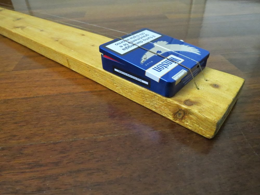
This is a magnetic levitator implemented using Atmega8 microcontroller.
Magnetic levitation is a method by which an object is suspended with no support other than magnetic fields.


To make a magnet levitate, an hall sensor is attached to a coil. The coil acts as an electromagnet, and the hall sensor measure the distance of the magnet from the coil.
The coil it is driven by PWM impulses, the closer the magnet is from the hall sensor, the bigger is the duty cycle and vice versa.
The coil works only if the magnet is in a certain range, out of this range no current flow through the coil, and the system is in is idle state.
The system has to mantain the equilibrium position of the magnet, the pull force of the coil has to be equal to the gravity force that pull the magnet to ground.

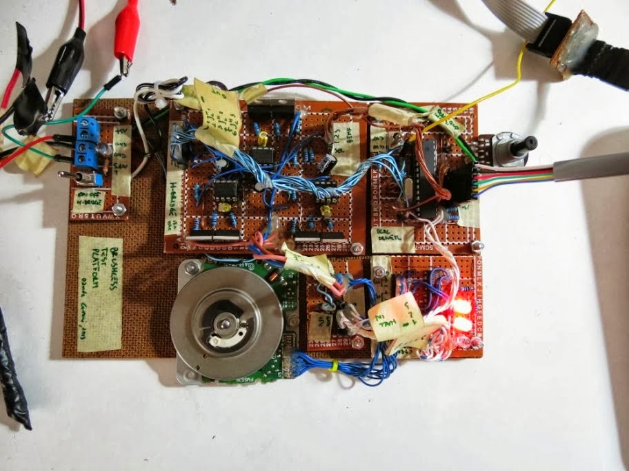
To stay on the budget, a small 12V 50N coil (ZYE1-P25/20) is used, with this coil the system can not lift heavy loads.
The hall sensor used it the Allegro A1302.
Because the heavy loads limitation, i've to put the hall sensor next to the coil, this solution produce a problem, the magnet can be pull even by the ferrite core of the coil, If it gets too close to the coil. To prevent this situation we have to emitting less current to the coil.
A bigger coil and a more sensible hall sensor can lift heavier load, and also the magnet can levitate far away from the coil.

An RGB led, next to the hall sensor, is powered on when the magnet is detected.


To adjust PWM intensity, a PID controller is used.
A proportional-integral-derivative controller (PID controller) is a generic control loop feedback mechanism (controller) that calculates an "error" value as the difference between a measured process variable and a desired setpoint. The controller attempts to minimize the error by adjusting the process control inputs.

The micro runs at 8Mhz, every 1ms the hall sensor it is checked, and the PWM for the coil is adjusted. The PWM period is 1953Hz.


The PID controller parameters, and other configuration options are stored in eeprom and can be edited by a software application connected through the UART connection. The software used for this functionality is avruartconfig.
All the configuration values could be changed through the UART connection for different coil / hall sensor / magnet hardware.


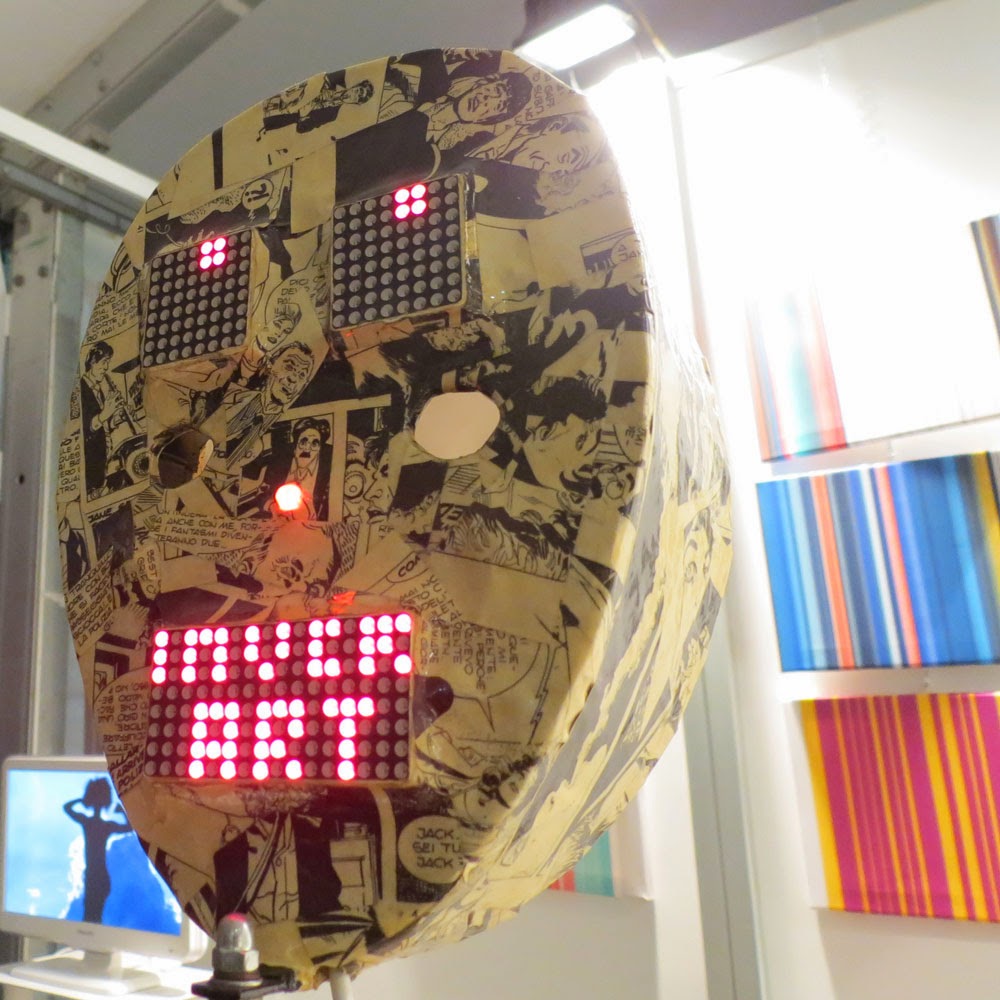
For an art fair next to my town, InverART 2013, a friend of mine, Paolo Crespi, build the sculptures you can see on the image above.


Code


Notes
  • read risk disclaimer
  • excuse my bad english

Sunday, November 24, 2013

Driving a DC motor using software PWM with AVR ATmega

Update to version 05

This library is an update of the software PWM driver you can find here:
http://davidegironi.blogspot.it/2013/03/controlling-dc-motor-speed-and_6.html
For DC motor information please look at the above link.


This update implements also progressive start / stop features.

So, with this one, you can drive up to 4 motors independently controlling:
  • speed
  • direction
  • slow start / stop


Changelog

  • 05: renamed timer macros, fixed max speed
  • 04: small fix to rampup
  • 03: small fix to velocity calculation, math.h lib can now be omitted, add a function that returns the current motor speed
  • 02: first version


Setup parameters are contained in dcmotorpwmsoft.h

This library was developed on Eclipse, built with avr-gcc on Atmega8 @ 1MHz.


Code


Notes
  • read risk disclaimer
  • excuse my bad english

Tuesday, November 12, 2013

Homemade 2 Guitar Strings Diddley Bow


The diddley bow is a string instrument of African origin made popular in America, probably developed from instruments found on the Ghana coast of west Africa. The diddley bow is typically homemade, consisting usually of a wooden board and a single wire string stretched between two screws, and played by plucking while varying the pitch with a metal or glass slide held in the other hand.

This is my homemade 2 Guitar Strings Diddley Bow.


This diddley bow is built using an "B" (.016), and a "D" (.032) acoustic strings, and a piece of wood.
You can tune this instrument as you want, and use any string you want, in the sample video i've used:
"B" (.016) tuned to F#, "D" (.032) to B.
Wooden board dimension is 82.5cm length, 9.0cm width, 2.2cm height.
The string action is 2.5cm.
Two piece of aluminum L are used as bridge and nut, dimension are: 2.5cm long side (make the diddley action), 1cm short side, 0.2cm thickness.
The tuning peg is a cheap one used for guitar. Two screws are used to direct strings from the nut to the pegs.
The guitar pridge is built using an aluminium cigaret box, it is opened, inside a piezo is glued to act as a pickup, wired to a 500k log pot, and a female 1/4" panel plug. The cigaret box is open and it rely on the bridge aliminium L.
Inside the cigaret box there is a piece of cloth to prevent piezo feedback.
Even it this diddley has no fret reference, the scale is set to 22".
It is painted using wood protective teak.


Notes
  • read risk disclaimer
  • excuse my bad english

Tuesday, November 5, 2013

A Passive Monitor Controller for Balanced / Unbalanced signals

Monitor Controller 01 is a passive studio monitor controller.


It can control volume for Balanced and Unbalanced signal monitor.
It has an output selector so you can choose between two set of monitor.
Also it has a mute switch to mute the output.

Technically this is a balanced attenuator pad, so it as a minimum reduction gain, which for the proposed schematic is -1.58dB.


A design like this can result in a high frequency loss for long output cables (>15mt).
As you can see, it's just need a logarithmic 10k dual pot, and a 4 1/4w 1k resistors, metal film 1% resistors are better, but you can use even carbon film 5% one without any audible issue.


Notes
  • read risk disclaimer
  • excuse my bad english

Monday, October 28, 2013

An AVR ATmega configurable production line counter

Updated to version 01b

This project here is a production line counter build on an ATmega 8 micro.


It has 4 digit seven segment display.
It can count from 1 to 9999 pieces.
(01b) Input can be delayed, so that every input recived will block the counter for an amount of time, to prevent double reading on too sensitive item sensors.

User can program it to emit an alarm when a number of items is reached.

Also a plus and minus button are present to adjust items count, if something has to be changed manually.
Holding the select button for a while make the counter reset.

To enter programming mode the select button have to be pressed while the device startup.

Setup parameters are contained in main.h, key.h and sevseg.h

This library was developed on Eclipse, built with avr-gcc on Atmega8 @ 8MHz.


Changelog
  • 01b: added the input delay capability
  • 01: first release


Code

Notes
  • read risk disclaimer
  • excuse my bad english

Monday, October 21, 2013

An ATmega countdown programmable timer

-- ref. 2012 --

This is an ATmega 8 based countdown programmable timer.


The timer alternates a "working" period, and a "pause" period. This is usefull if you have to run a device at a predetermined interval of days, for an amount of minutes you can chose.


It shows time using a double seven segment display.
User can select how much time to spend during the working and pause periods.

Periods can be selected from predefined values, stored in the hex firmware.
The pause period is expressed in days, the working in minutes.

There are five buttons:
  • pause +/- select the pause period
  • work +/- select the working period
  • start/stop iterate through perdiods
Both period are stored into internal avr eeprom, so that if the main power goes down, user settings are restored at next bootup.

The green led is on during the work period.

Setup parameters are contained in main.h

This library was developed on Eclipse, built with avr-gcc on Atmega8 @ 1MHz.


Code

Notes
  • read risk disclaimer
  • excuse my bad english

Sunday, October 13, 2013

vettev, an Open Source Veterinary Management Software

vettev is an Open Source Veterinary Management Software.


vettev is a complete solution to manage you veterinary clinic.
You can trace you customer and animal records, loading treatments, scheduling appointments, doing reports, and billing managment.
vettev features also a client-server architecture, it means that you can have access on multiple computer at the same time.

Please find further information and download link here: https://sourceforge.net/projects/vettev/

Monday, September 30, 2013

A simple brushless sensorless motor driver for AVR Atmega

Brushless electric motor (BLDC motors) are synchronous motors that are powered by a DC electric source via an integrated inverter/switching power supply, which produces an AC electric signal to drive the motor.


For an introduction to BLDC motors, please look at my sensored motor driver post, here: http://davidegironi.blogspot.it/2013/09/a-simple-brushless-sensored-motor.html


For this project, I've implemented a simple brushless sensoreless motor driver for AVR Atmega. The code i propose it's not perfect, and can be improved, but for the needs i had it works.

The motor can be controlled in speed and direction (clockwise and anti-clockwise).

This project use open loop startup and bemf zero crossing detection method with ADC.
Speed change can be done only when motor is not running, ADC is used during spinning phase in zc detection so it can not be used during the motor spinning, but digital speed changing can be implemented.
ZC threshold current should be defined by user depending on the motor type.

User has to setup the port used to read the the bemf current. Also the timer interrupt and prescaler should be setup for different running frequency.
The running step for the motor are defined as default, anyway user can change it to fit any motor.


A sample main routine is provided to help you understand how the library works.

The same test board of sensored library post is used, reported here the schamatics, for further info look at the sensored library post.

Setup parameters are contained in bldcsensorless.h

This library was developed on Eclipse, built with avr-gcc on Atmega8 @ 8MHz.

Code
Notes
  • read risk disclaimer
  • excuse my bad english

Sunday, September 15, 2013

A simple brushless sensored motor driver for AVR Atmega


Brushless electric motor (BLDC motors) are synchronous motors that are powered by a DC electric source via an integrated inverter/switching power supply, which produces an AC electric signal to drive the motor. Additional electronics control the inverter output amplitude and waveform (and therefore percent of DC bus usage/efficiency) and frequency (i.e. rotor speed). Because the controller must direct the rotor rotation, the controller requires some means of determining the rotor's orientation/position (relative to the stator coils). Some designs use Hall effect sensors or a rotary encoder to directly measure the rotor's position, others measure the back EMF in the undriven coils to infer the rotor position, eliminating the need for separate Hall effect sensors, and therefore are often called sensorless controllers.


The following explanation is taken from "AVR443: Sensor-based control of three phase Brushless DC motor" sheet.
Theory of operation: A three phase BLDC consists of a Stator with a number of coils. The fundamental three phase BLDC motor has three coils. Usually the three coils are referred to as U, V and W. In many motors the fundamental number of coils are replicated to have smaller rotation steps and smaller torque ripple. The rotor in a BLDC motor consists of an even number of permanent magnets. To simplify the explanation of how to operate a three-phase BLDC motor a fundamental BLDC with only three coils is considered. To make the motor rotate the coils are energized (or “activated”) in a predefined sequence, making the motor turn in one direction, say clockwise. Running the sequence in reverse order the motor run in the opposite direction. The direction of the current determines the orientation of the magnetic field generated by the coil. The magnetic field attracts and rejects the permanent magnets of the rotor. By changing the current flow in the coils and thereby the polarity of the magnetic fields at the right moment – and in the right sequence – the motor rotates. Alternation of the current flow through the coils to make the rotor turn is referred to as commutation. A three-phase BLDC motor has six states of commutation. When all six states in the commutation sequence have been performed the sequence is repeated to continue the rotation. The sequence represents a full electrical rotation. For motors with multiple poles the electrical rotation does not correspond to a mechanical rotation. A four-pole BLDC motor uses two electrical rotation cycles to per mechanical rotation. When specifying the number of Rotations Per Minute subsequently, the number of electrical rotations is referred to unless otherwise mentioned. The most elementary commutation driving method used for BLDC motors is an on-off scheme: A coil is either conducting (in one or the other direction) or not conducting. The strength of the magnetic field determines the torque and speed of the motor. For BLDC motors the commutation control is handled by electronics. The simplest way to control the commutation is to commutate according the outputs from a set of position sensors inside the motor. Usually Hall sensors are used, but even back EMF can be used to detect the stator position. A common commutation is the one represented by the image below.


For this project, I've implemented a simple brushless sensored motor driver for AVR Atmega. The code i propose it's not perfect, and can be improved, but for the needs i had it works.

Using this library, the motor can be controlled in speed and direction (clockwise and anti-clockwise).
The running step for the motor are defined as default, anyway user can change it to fit any motor. Below you can find the commutation sequence (for clockwise and anti-clockwise rotation) i've used:


User has to setup the port used to read the hall sensor, and the port to control the FET status. Also the timer interrupt and prescaler should be setup for different running frequency.

A sample main routine is provided to help you understand how the library works.

To test this project i've used a brushless motor taken from a cd-rom, it is connected to a LM339 voltage compartor to build an encloder. You can find connection circuit below.


The power drive stage for the brushless motor is build using IRF640 mosfet and IR2101 high and low side driver. The complete schematics below:


Note that even a back EMF wiring are present there, if you just want to use hall sensor you can skip those connections. Also an external crystal is connected just to test the circuit at 16Mhz, even if tests are done at 8Mhz.

Setup parameters are contained in bldcsensored.h

This library was developed on Eclipse, built with avr-gcc on Atmega8 @ 8MHz.

Code
Notes
  • read risk disclaimer
  • excuse my bad english

Monday, September 2, 2013

AVR Atmega dehumidifier controller board, update

This project is an update to the previous dehumidifier based you can here: http://davidegironi.blogspot.it/2013/04/avr-atmega-dehumidifier-controller.html
This update adds some usefull functions.


The main issue that i've fixed is the microcontroller crash, that happens sometimes. I've noticed that sometimes the controller stop running, crash or doesn't works as expected.
After some experimets, i've noticed that probem was due to Electromagnetic Interference (EMI), EMI happens when the compressor and fan starts or stops.
I've solved this issues by:
  • insulating relays with metal tape
  • outdistance relays from the microcontroller
If you look at the image below you can see that relays are not distant from the microcontroller.


To build a more secure controller, i've added a watchdog control to reset the microcontroller if anything goes wrong.

Another improvement to the previous design is the additions of a minimum off/on time to prevent the compressor to be switched on and off in a short time. Some compressor may get broken if those timed function does not exists.

Finally i've switched the DHT11/22 sensor with an AMT1001 sensor. The AMT1001 sensor is less sensible to EMI, and it has analogic output.


Changelog
  • 1.0.9: added offset calibration for humidity/temperature sensor
  • 1.0.8: fix minimum on/off compressor time with antifrost temperature.
  • 1.0.6: DHT switched to AMT1001, add watchdog, add minimum on/off compressor time.
  • 1.0.4: DHT library update to prevent blocking.
  • 1.0.3:first release.


Code

Notes
  • read risk disclaimer
  • excuse my bad english

Monday, August 26, 2013

Google Drive Download Widget, a download button generator

Google Drive Download Button is an online app that builds a download button you can use in your website.
  1. Set the sharing settings for your file to "Public on the web" or "Anyone with the link"
  2. Copy the "sharing link" at the top of your Google Drive sharing window and paste it in the textbox, or copy the "fileId" in the textbox
  3. Click the "build button".
  4. Use the HTML code in your website
This small app makes use of the Google Drive API to check the file existance and get the file size.
If you would like to install this app you only have to generate a API key from the Google API Console, enable Drive API service, generate a Server or a Browser key and then paste your API key in the functions.js file.

That's it :)


Code
Notes
  • read risk disclaimer
  • excuse my bad english

Monday, August 19, 2013

An optical dust meter that uses the GP2Y1010AU0F sensor library made with AVR Atmega

This project is a dust detector that use the GP2Y1010AU0F sensor.
Attached you can also find the GP2Y1010AU0F sensor library for AVR Atmega.


GP2Y1010AU0F is a dust sensor by optical sensing system. An infrared emitting diode (IRED) and an phototransistor are diagonally arranged into this device. It detects the reflected light of dust in air. Especially, it is effective to detect very fine particle like the cigarette smoke.


Unfortunately the datasheet does not tell anything about the particle size detected, it just tell us that this sensor is for fine particle like cigarette smoke, that is to say about 0.5micron.

This sensor output a pulse-driven wave form that we can read using the ADC of our microcontroller to convert it to usefull data.
Looking at the figure 2 of the GP2Y1010AU0F datasheet we can derive the method to convert the output data.
Note that the sample time should be 280us to perform the correct reading, and this delay should consider that ADC conversion takes 13 ADC clock cycles, so ADCtime(s) = (1/ADCclock)*13 = (1/FCPU/ADCprescaler)*13.
So to perform reading at correct time we have to subtract the time taken by ADC convertion to the suggested time.
As example lets consider a micro running at 8Mhz, with ADC prescaler set to 64
(1/(8000000/64))*13 = 0.000104s = 104us
280us - 104us = 176us
we have to delay 176us and then we can read the sensor output voltage.
Once we have obtained the sampling voltage, we can convert it to mg/m^3 using the fig 3 of the GP2Y1010AU0F datasheet, that shows the dust density (mg/m^3) related to output voltage of the sensor (V).
Chris Nafis does some interesting consideration on this sensor in his Air Quality Monitoring page. Also he does linear interpolation and find the graph obtained the slope and the base for the convertion function.


Code

Notes
  • read risk disclaimer
  • excuse my bad english

Thursday, August 1, 2013

AVR Atmega multiple 8x8 led matrix using MAX7219

This library implements a 8x8 led matrix for AVR Atmega.


It uses just one MAX7219 serial input/output common-cathode display drivers and 3 ports.
MAX7219 can refresh leds leving more resources to microcontroller.
This library uses MAX7219 without the need of SPI. User can setup scan limit and intensity setup.
Multiple led matrix can be attached.


With simple functions, it gives your the ability to:
  • power on / off a single led
  • setup a selected row
  • setup an 8x8 matrix
Setup parameters are stored in file ledmatrix7219d88.h


Code

Notes
  • read risk disclaimer
  • excuse my bad english

Monday, July 22, 2013

AVR Atmega MAX7219 7-segment / led matrix display driver library

Updated to version 03

The MAX7219/MAX7221 are compact, serial input/output common-cathode display drivers that interface microprocessors to 7-segment numeric LED displays of up to 8 digits, bar-graph displays, or 64 individual LEDs.


MAX7219 prevents the use of microprocessor resorces, indeed all the logic to drive LED drivers is built inside this small IC.
This library use 3 ports to control MAX7219 ic. It can control more than one ic, without the need of SPI. User can setup scan limit, intensity and other parameter of the ic.


Setup parameters are stored in file max7219.h

This library was developed on Eclipse, built with avr-gcc on Atmega8 @ 1MHz.


Changelog

  • added atomic enabler on shift out function
  • added get status functions
  • first version

Code

Notes
  • read risk disclaimer
  • excuse my bad english

Sunday, July 14, 2013

Mi Chiamavo Eva

This times is not about electronics, it'a about my brand new album!


You can listen to, and download it for free here: http://www.jamendo.com/it/list/a123309/mi-chiamavo-eva

This is the album website: http://michiamavoeva.altervista.org/

Below a video from one of the album songs.


It's all played, recorded, mixed and mastered by me.

I would like to thanks all the peaple who help me in developing this project, the "EvaGomma", Fausto and Mauro, Teo Cava, Teo Ellio and Elena.
Also thanks to Dave Pensado's http://www.pensadosplace.tv/, there I've found so many helpfull lessons that improved my mixing skills.

Monday, July 8, 2013

An AVR Atmega LCD Menu builder library

Updated to version 02

lcdmenu1 is a simple and small lcd menu builder for AVR Atmega.


It works with only 4 buttons (up, down, right, left), additional buttons can be added.
It can also store values to eeprom


User can use button up and down to list menu categories, right and left to browse child and parent.
If an item is selected, the right button makes the menu enter in edit-mode.
In this mode button up and down changes the item value, left exit without save to eeprom, right exit and save to eeprom.
The menu costructor is based upon Dean Camera micro-menu. It works on 2x16 lcd using the Peter Fleury lcd library for HD44780, but it can also be change to fit other lcd resolution.
It is test on 2x16 HD44780 device, sample code is provided.

The main function is the builder function:

lcdmenu1_makemenu(name, next, prev, parent, sibling, selectfunc, enterfunc, exitfunc, text);
name is the name of the menuitem
next is the pointer to next menuitem
prev is the pointer to the prev menuitem
parent is the parent of the menuitem
sibling is the child of the menuitem
enterfunc is the function to be called when user enter this menuitem
exitfunc is the function to be called when user exit this menuitem
text is the text view on lcd for the menuitem

The sample  code provided build menu item, menu folder, menu subfoder.


This library was developed on Eclipse, built with avr-gcc on Atmega8 @ 8MHz.


Code

Notes
  • read risk disclaimer
  • excuse my bad english

Tuesday, July 2, 2013

AMT1001 humidity and temperature sensor library for AVR Atmega

The AMT1001 is a Resistive-type humidity and temperature sensor/module.


It can detect humidity from 20 to 90 %RH with and accurancy of +-5%RH.
Temperature sensing is built using an NTC thermistor.


This library here implements a way to get humidity and temperature data from this sensor.
Setup parameters are stored in file amt1001.h

Humidity conversion formula is based upon graph 1 of the datasheet (see below).


Temperature conversion it is based upon the Beta Model Equation, given the know beta printed above the amt1001 sensor.
Also two Open Office helpers are provided to built the lookup table used for ADC to temperature conversion and for beta estimation from points.

This library was developed on Eclipse, built with avr-gcc on Atmega8 @ 1MHz.


Code

Notes
  • read risk disclaimer
  • excuse my bad english